![]()
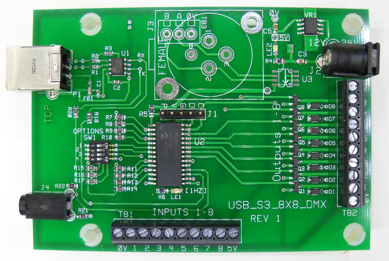
USB-S3-8x8
Features:
This board was designed with 'low impedance' drivers. The outputs can drive relays or LED's. Either USB or Serial (Series 3 BrightSigns only for serial).
Serial Setup (stereo cable): In BrightAuthor, select Presentation Properties, Serial Setup and select port0. Set the port to 38,400 baud. Select 'Invert Serial' for the serial port. Note: After the BrightSign boots, the tip of the stereo connector should measure about 5V (to the barrel). Without this selection, the tip will measure about 0V and this will be the wrong polarity for the USB-S3 board. Rev 5 firmware now has an Invert/Non-Invert selection. See the 'Options' below.
USB Setup: In BrightAuthor, select Presentation Properties, Serial Setup and select port2. Set the port to 38,400. The USB-Serial Interface is handled by a Prolific USB-Serial converter and appears as a serial port in BrightAuthor.
Note: USB can be used to power the board with 5V if using the TTL connection for serial interface. The TTL connection overrides the USB.
Operation:
The Firmware allows for multiple inputs low at the same time. I.E. If input 1 goes low ('1' is reported), then input 2 goes low (while input 1 is held low), then input 2 will be reported. If any 'active' Input (switch) opens then closes, it will be reported as a new input. I.E. suppose input1 is closed and input2 is closed and opened multiple times. A '2' will be sent with each successive switch closure. This logic is for all inputs. With Rev 2.x firmware, a single switch can be used to show closed and open. If you want to detect a door or drawer opening and then closing, arrange the switch to close when the door or drawer opens, and then the switch opens when the door or drawer is closed.
*********Output Control Commands (Lights):
Note: The brackets or the comma's are not part of the byte sequence. Use the 'Serial Send Byte, Comma Separated command to send the bytes.
Outputs are fade control enabled (dimming). Use this table of bits to determine the number to send from the BrightSign to control the outputs.
Connect Loads between 'Output' and '+V' on the output terminal block.
Note: A 'Fade' of zero, causes instant change in Brightness (no fade).
Note: Fade is the number of milliseconds to make a change in Brightness. A
fade value of 20 will take 20 milliseconds to change to the next Brightness.
So, to change from 0 to 255 (minimum to maximum Brightness) with Fade=20 (20
milliseconds per step of change) will take 20 * 255 or 5.1 seconds.
Note: The brackets are not part of the byte sequence.
Note: LED's are very responsive to PWM changes. A change from value of
1 (1/255 on time) to 2 (2/255) on time is 100% change is step. This is
very noticeable at very low PWM values. I recommend you start with a
brightness value of 10 then set the brightness with fade.
I.E. (CMD1, Output1, Brightness=10, Fade=0, 204) = 001, 001, 010, 000, 204
Then send a second Command 1 to adjust the brightness with fade (Brightness 128,
fade=040) = 001, 001, 128, 040, 204
Command1: To control any of the 1-8 Outputs (Command1), set the 'Select_Bits'
to match the outputs. Set the 'Fade' for those Outputs, Then set the
Brightness for those Outputs.
I.E. to turn on Output1+Output8 (to the maximum brightness=255, fade
rate=20), Command1=[1,129,255,20,204]
I.E. to turn off Output8 (brightness = 0, fade rate=20),
Command1=[1,128,20,0,204]
I.E. to Turn off Output1 (instant) (Select_Bits = 1, brightness = 0, Fade=0),
Command1 = [1,1,0,0,204]
Options (4-Pole Option Switch)
SW1-1 On, selects 'Not HMS Protocol' (the single byte protocol to control outputs). Off selects the HMS Command Protocol
SW1-2 (Rev 5 firmware) ON selects 'Invert serial signals'. Use this selection if using a computer RS232 port or if you don't want to invert the serial signals from the BrightSign. With this selection the tip of the stereo jack should be negative or about 0 volts in standby.
SW1-3 ON selects a 'Reflect Diagnostic'. The Inputs are reflected to the Outputs. I.E. when input 1 goes low, output 1 is turned on.
SW1-4 ON selects a cycle diagnostic. Outputs are sequentially turned on at 1 second intervals. I.E. output 1, then output 2.
| Note: External Supply Voltage: An External Power Supply is needed to power the loads on the output connector. Do not connect any loads that have their own power that exceeds the power as applied to the board using the 'Ext. Power Connector'. Doing so may result in damage to the board. I.E. Suppose that 12 volts is supplied to this board and you have a relay board with it's own power of 24Volts DC that powers the relays. The 24VDC will feed back into the board via the foldback diodes. Note: Foldback diodes are required for inductive loads such as relays or small motors. |
Auto Polarity: ('AUTO-POL' sticker on the board) firmware has autodetect for the serial polarity. The board configures the serial polarityconnection automatically for the USB or TTL connection. If using USB you need to send a null byte [serial.sendbyte(0)] to synchronize the board serial polarity.
Author: Richard Harkey
Revised: August 17, 2024