![]()
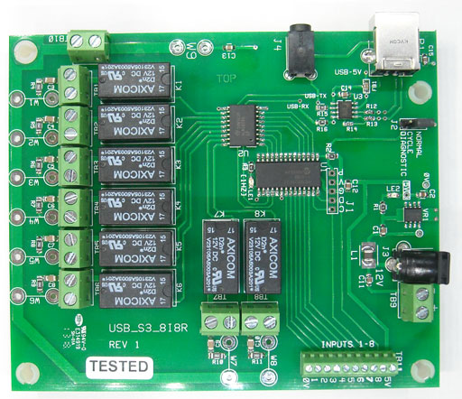
USB-S3-8I-8R
Features:
Operation:
The Controller (BrightSign or other controller) has to send a single bytes to control the 8 relays. The bits of the 8 bit byte controls the 8 relays.
At any time, the Brightsign sends out the 'Set Port String', then the relays will turn on according to the bit pattern of the 'Port Byte'. I.E. Bit 0 of the byte set to '1', will turn on Relay1. Bit 7 of the byte set to '1' will turn on Relay 8.
I.E. To control the relays, send the byte that represents the bits of the relays (see table below). The single byte turns on/off the relays according to the bits!
Just add the decimal numbers together to get the bits set that you want. Setting all bits on is 255d (decimal). Setting bits 0 and 7 on is 128+1 or 129 decimal
Note: See the schematic for the use of the 'bus' connections. Bus lines are present to use the board 12 volts for easy connection to drive external loads. Or, 120VAC/240VAC can be applied to the bus and then jumpers made (soldered) to connect the bus voltage to the relay contacts.
DC Voltage 'Large Inductive loads' may require a diode to be placed across the load. Without the diode, the inductive 'kick' when the relay is turned off can reset the microprocessor! AC loads require a snubber network across the contacts of the relay on the HMS board. The board has built in snubber networks for this purpose. The snubber networks may be insufficient for preventing reset when driving highly 'inductive' DC loads such as a 'contactor relays' or motor.
Series 3 & 4 Compatible: The 3.5mm stereo jack can be used with the BrightSigns that have the 3.5mm stereo jack (TTL Port).
Auto Polarity: ('AUTO-POL' sticker on the board) firmware has autodetect for the serial polarity. The board configures the serial polarityconnection automatically for the USB or TTL connection. If using USB you need to send a null byte [serial.sendbyte(0)] to synchronize the board serial polarity.
| Note: External Supply Voltage: An External
12 Volt, 1amp Power Supply is needed to power the relays. VR1 (voltage
regulator) will supply 5V if the TTL port is utilized for serial interface. Note: Not recommended for controlling power supplies as the inrush of current can fuse the contacts! |
Author: Richard Harkey
Revised: August 17, 2024