![]()
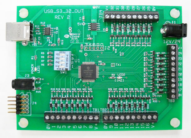
USB-S3-32-OUT
32 Outputs (Expandable to 64,96 or 128 outputs)
Features:
Description of Operation:
This board is used to interface to a BrightSign with either a USB port or a
Serial Port. HMS Protocol or simple byte protocol for control of outputs.
This board was designed with 'low impedance' drivers. The outputs can drive relays, small motors, LED's or Incandescent Lights.
Serial Setup (stereo cable): In BrightAuthor, select Presentation Properties, Serial Setup and select port0. Set the port to 38,400 baud. Select 'Invert Serial' for the serial port. Note: After the BrightSign boots, the tip of the stereo connector should measure about 5V (to the barrel). Without this selection, the tip will measure about 0V and this will be the wrong polarity for the USB-S3 board.
USB Setup: In BrightAuthor: select Presentation Properties, Serial Setup and select port2. Set the port to 38,400. The USB-Serial Interface is handled by a Prolific USB-Serial converter and appears as a serial port to the BrightSign.
Serial Protocol: To synchronize transmission to the HMS board, a 20 millisecond 'break' or 'pause' is required. After the 'break' the HMS board 'receive bytes pointer' resets to zero. The next byte received after the 'break' is the first byte of the next controlling sequence.
Address Selection:
The switch on the Board (SW1) is used to set the address of the board (see the table below).
| SW1-1 | SW1-2 | ADDRESS | OUTPUTS | Control Bytes |
| OFF | OFF | 0 | 1-32 | 1-4 |
| ON | OFF | 1 | 33-64 | 1-8 |
| OFF | ON | 2 | 65-96 | 1-12 |
| ON | ON | 3 | 97-128 | 1-16 |
SW1-3 'Off' Selects the 'Byte Protocol. 'On' selects the HMS Protocol with brightness and fade.
Byte Protocol: Each byte has 8 bits so it takes 4 bytes to control 32 outputs. The bits of the byte are used to turn the outputs on or off. I.E. a value of 128 (10000000 binary) turn on output 8 and outputs 1-7 are turned off. A value of 127 (01111111 binary) turns on outputs 1-7 and turns off output 8. With this scheme any combination of outputs can be turned on or off.
HMS Protocol: This is a 'command protocol' that controls Brightness and Fade for each output. The protocol consists of 5 bytes. The command#, select bits, Brightness value, fade rate, and verify byte.
| CMD# | Outputs | Commandd Bytes |
| 1 | 1-8 | 1,Select bits,Brightness,Fade,204 |
| 2 | 9-16 | 2,Select bits,Brightness,Fade,204 |
| 3 | 17-24 | 3,Select bits,Brightness,Fade,204 |
| 4 | 25-32 | 4,Select bits,Brightness,Fade,204 |
| 5 | 33-40 | 5,Select bits,Brightness,Fade,204 |
| 6 | 41-48 | 6,Select bits,Brightness,Fade,204 |
| 7 | 49-56 | 7,Select bits,Brightness,Fade,204 |
| 8 | 57-64 | 8,Select bits,Brightness,Fade,204 |
| 9 | 65-72 | 9,Select bits,Brightness,Fade,204 |
| 10 | 73-80 | 10,Select bits,Brightness,Fade,204 |
| 11 | 81-88 | 11,Select bits,Brightness,Fade,204 |
| 12 | 89-96 | 12,Select bits,Brightness,Fade,204 |
| 13 | 97-104 | 13,Select bits,Brightness,Fade,204 |
| 14 | 105-112 | 14,Select bits,Brightness,Fade,204 |
| 15 | 113-120 | 15,Select bits,Brightness,Fade,204 |
| 16 | 120-128 | 16,Select bits,Brightness,Fade,204 |
| 17 | All Outputs Off! | 17,204 |
HMS Protocol Notes:
Sample Command: 2,129,255,20,204. This would turn on outputs 9 and 16 (Select Bits = 10000001b or 129 decimal). Brightness of 255 is full on and fade of 20 fades on or off at 20 milliseconds per step of change. So, to fade from 0 to 255 brightness at 20 milliseconds per step is 5100 milliseconds or 5.1 seconds to go from 0 to 255 brightness.
SW1-4 (ON) is a cycle diagnostic. One of each 8 outputs of each output port is turned on sequentially. I.E. 1,9,17,25 are on, then 2,10,18,26 are on and so forth.
Note: When using the expander boards (to add additional outputs of 64,96 or 128) two cables are provided to provide the interconnection. The cables connect the serial data to each board and provides a jumper for the +V. However, if you need to drive more than 5 amps total (all boards), use the output connector 0V and +V on each board to connect your power supply (or power supplies). All power supplies have to have the same ratings. The 2.1mm power jack is rated at 5 amperes.
Note: This Specification Sheet applies to both the USB-S3-32-OUT and the 32-OUT-EX (expander board). The -EX board has no USB components as the USB or Serial signal is coupled to the 32-OUT-EX via a 10 pin cable. This cable connect 0V, RX (the receive signal from USB or Serial) and +V (12/24V). If driving more than 5 amps total, each expander board should be supplied with its own +V power supply. Use the power jack or the terminal block to make the additional power connections.
Note: The output transistors drive the outputs low. The loads should be connected from +V to the output drive terminal block. Then when the output is driven low, the load will conduct from output (0V) to +V.
![]() USB_CYCLE_32OUT.BRS (rename to autorun.brs and put in the root directory of
the SD card). This file cycles outputs to all on, then instant off using
command 17. I.E. 1,9,17,25 are turned on, then 2,10,18,26 are also turned
on until all 8 outputs of each ports are turned on.
USB_CYCLE_32OUT.BRS (rename to autorun.brs and put in the root directory of
the SD card). This file cycles outputs to all on, then instant off using
command 17. I.E. 1,9,17,25 are turned on, then 2,10,18,26 are also turned
on until all 8 outputs of each ports are turned on.
Auto Polarity: ('AUTO-POL' sticker on the board) firmware has autodetect for the serial polarity. The board configures the serial polarityconnection automatically for the USB or TTL connection. If using USB you need to send a null byte [serial.sendbyte(0)] to synchronize the board serial polarity.
Author: Richard Harkey
Revised: August 17, 2024