![]()
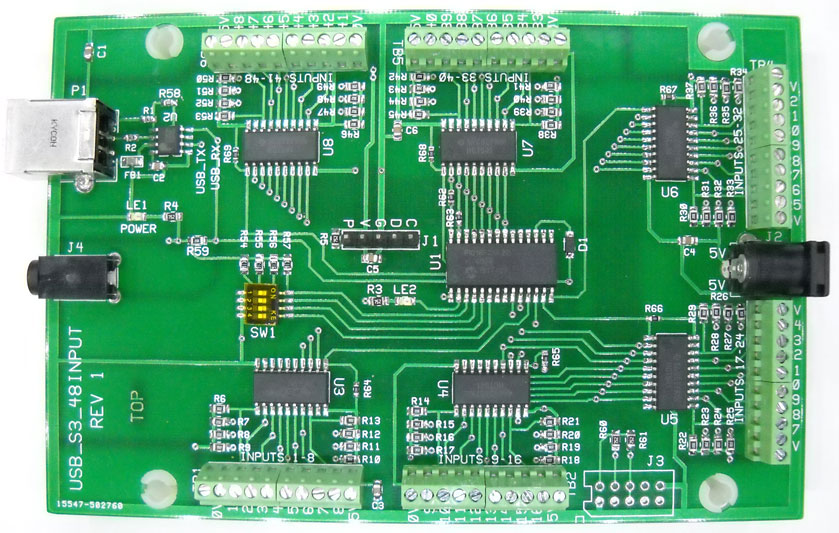
48 input USB or 'S3 Serial' (Interface Board)
Features:
Note: The USB port of the HMS Board appears as a Serial Port to the BrightSign. The board will appear as Serial Port 2. Be sure to Select 'Preferences'/Interactive in BrightAuthor and set Port 2 to 38,400 (all other check boxes can be left as the default.
Note: If using the 3.5mm Serial Port Connection of the BrightSign, External 5V is required to power the board. The 3.5mm serial connection appears as Port 0. Be sure to set the port to 38,400 baud in 'Preferences/Interactive' in BrightAuthor. Also, select the box (Invert Serial). In standby (BrightAuthor is running the serial port), the TX pin of the serial connector should be low (close to 0V).
Mode 0 (SW1 all off) When an input is grounded (set low), a string is sent out that represents the input (BrightAuthor compatible). If multiple inputs are activated, successive inputs are reported. I.E. If input 1 is closed, the "1" is reported, if input 9 closes also, then the new input "9" is reported. When all inputs go high, then a zero is reported (switches have all been released).
The strings are:
Mode 1 (SW1-1 on)
Similar to above but '+' or '-' are sent. I.E. If input1 is closed "+1",13 is sent (all strings follow with a carriage return). When Input 1 is released then "-1",13 is sent.
Mode 2 (SW1-2 On)
Similar to Mode 1 except the reported number is "49" to "96" for inputs 1 to 48.
Mode 3 (SW1-1 and SW1-2 On)
Similar to Mode 1 except the reported number is "97" to "144" for inputs 1 to 48
Mode 4 (SW1-3 On)
Similar to Mode 1 except the reported number is "145" to "192" for inputs 1 to 48
Mode 5 (SW1-3 and SW1-1 On)
Similar to Mode 1 except the reported number is "193" to "240"
Mode 6 (SW1-3 and SW1-2 On)
Similar to Mode 1 except the reported number is "241" to "288".
Mode 7 (SW1-3, SW1-2, SW1-1 On)
Similar to Mode 1 except the reported number is "289" to "336"
Note: All Modes 1 to Mode 7 are strings with "+" or "-" inserted before the number and all strings are followed with a carriage return (13).
Note: It is 'highly suggested' that you view the results of the switch closures on your computer using serial interface firmware. As stated above, the USB port will be utilized as a serial port. So when connecting a computer to the HMS board, the driver for USB-Serial will be loaded.
![]() RS232_Slides.BRS (BrightScript File)
RS232_Slides.BRS (BrightScript File)
This script written for the 16 input board in 'ascii' mode and will work for inputs 1-16 on the 48 input board. It will play a slide to match the input number (slides 1 through 16).
Un-Zip this file to the Root Directory of your SD card and rename the file RS232_Slides.BRS to autorun.brs. All of the slides should be in the 'Slides' sub-directory.
Author: Richard Harkey
Revised: August 17, 2024