![]()
 |
 |
|
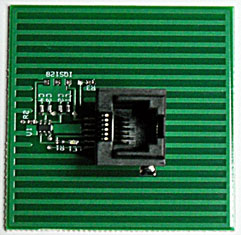
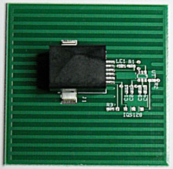
Component Side '-V' |
Component Side '-H' |
|
|
|
|
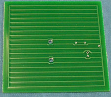
Proximity/Touch Side |
Proximity/Touch Side |
AZ-Sense2-V |
AZ-Sense2-H |
Features:
Use this touch sensor with the 'GPIO RJ11-4' adapter or GPIO-RJ11-8 adapter (shown below).
This proximity 'capacitive touch sensor' can sense thru a variety of materials. Just stick on behind the glass, plywood or plastic panel, turn on power, you have a touch sensor located behind your display panel. This sensor has been tested with 1.5 inches MDF material. Because the sensor self calibrates on power-up, it automatically adjusts to environment variations not only when power is applied. It also has 'long term' stabilizing algorithm built in. Because the sensor self calibrates to materials on power-up, it takes about 5 seconds for the sensor to stabilize. The BrightSign takes 20-40 seconds to power-up so the sensor is ready before the BrightSign is ready.
Testing with Glass (very similar results with 3/4 inch thick MDF):
The sensor can be programmed for 'touch sensing' instead of proximity sensing. If you want the sensor to activate after you touch a surface, you will have to contact HMS Electronics Technical support with the specifics of your materials. Several 'trial and error' sensor modules may be needed to determine which is best suited for your application.
Note on construction materials: Glass or Plastic do not have any effect on the sensor sensitivity. Wood and artificial wood (like MDF) have capacitive characteristics and can affect the sensor. Our testing of the sensor indicates that due to the 'Dynamic Calibration' of the sensor, many materials have very little effect on the proximity detection. However, any conductive material (like foil, metal plates and so forth) that is place in the vicinity of the sensor can effect the operation of the sensor. Do not put the sensor behind metal unless the metal is used as a 'touch surface'.
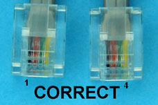
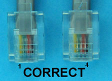
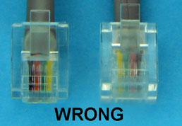
Note on the Phone Cable: The phone cable has to be polarized if mating with a phone jack at the GPIO! Meaning that the connectors on both ends have to have the same connection. I.E. if pin 1 of the connector on 'End1' has a black wire, then pin 1 of the connector of 'End2' has to also have a black wire. This 'polarization' applies to each of the pins of the connector. Typical connections pin 1 to pin 4 are Black, Red, Green Yellow. It doesn't matter if the connection are reversed (Yellow, Green, Red, Black) as long as both connectors are wired the same. Swapping the wires will result in destroying the sensor.
Note on Paint: If paint is required on the 'proximity' side of the sensor, use a latex paint. Using paint with metallic particles in the paint may alter the characteristics of the 'proximity touch sensor'.
Wire Identification:
 |
 |
|
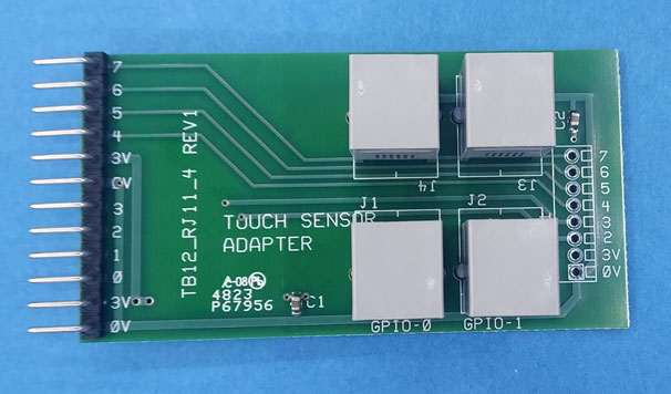
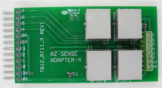
TB12-RJ11-4 |
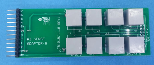
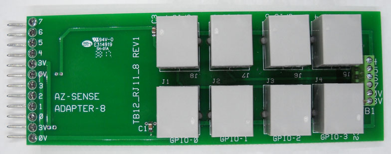
TB12-RJ11-8 |
 |
 |
|
TB12-RJ11-4-TB Phoenix Adapter with Terminal Block |
TB12-RJ11-8-TB |
These adapters are designed to attach to the Proximity/Touch Sensors to the Phoenix connector of the BrightSign. Up to four or eight sensors can be connected to the BrightSign using these adapters.
TB12-RJ11-4: The four Sensor connectors goto GPIO 0 thru 3. The Optional Terminal block connects to GPIO 2 thru 7 giving the designer the option of using other external triggers.
TB12-RJ11-8: Up to eight Sensors connecto to GPIO 0 thru 7. The Optional Terminal block connects to GPIO 4 thru 7 giving the designer the option of using other external triggers.
Contact HMS Electronics 'Technical Support' for questions related to the 'Capacitive Touch Sensors'.
The current draw on the sensor module is very low so cable length has almost no effect on sensor operation. Maximum cable length has not been determined. However, 100 feet (30 meters) is a distance that the module should work with. We suspect that the sensor could be 300 feet (100 meters) or more.
The RJ11 phone cable ends need to have the same 'polarity'. Meaning, all pins of the plugs need to have the same color wire in both ends. Here are a couple of pictures to help with identification of 'polarized' phone cables.
Note: If not using the TB12-RJ11-4 or TB12-RJ11-8, then cut and strip the 4 wires for attaching to a terminal block.
RJ11-1. Tie all 3.3V-5V wires together and connect to 3.3V or 5V on the HMS Interface board.
RJ11-2. Connect each 'Sensor Output' to the appropriate input of the HMS Interface board.
RJ11-3 + RJ11-4. connect both wires to 0V on the HMS Interface board.
Note: For 'Legacy BrightSigns' use the DB15-TB10-3V adapter for direct connection to the BrightSign.
Author: Richard Harkey
Revised: August 15, 2024