![]()
RF-TRP-REMOTE
Wireless Control for the BrightSign GPIO
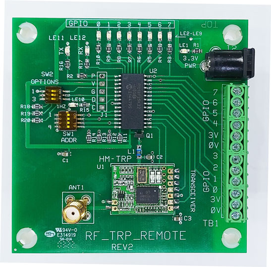
Note: Antenna Included
This board is used to 'remote' most HMS interface boards with phoenix connector (pins) or make direct connections to the terminal block.
Channel Selection |
|||
| SW1-1 | SW1-2 | SW1-3 | Channel# |
| Off | Off | Off | 1 |
| On | Off | Off | 2 |
| Off | On | Off | 3 |
| On | On | Off | 4 |
| Off | Off | On | 5 |
| On | Off | On | 6 |
| Off | On | On | 7 |
| On | On | On | 7 |
Note: SW1-4 is used for a built in cycle diagnostic. If on, then this board sets all GPIO to outputs and turns on 1 output at a time and sends the new state of the GPIO to the LOCAL board. Therefore, the local board should be set to slave (normal mode)
SW2-1 & Sw2-2 'Off' (master mode): This selects all 8 GPIO pins of this 'Remote' as inputs. This 'Remote' board transmits the 8 data bits to the 'Local' receiver.
SW2-1 On: This selects 4x4 operation (SW2-2 is ignored): GPIO-0 thru 3 are sent to the 'Local' board. GPIO-4 thru 7 are received from the 'Local' board. This operation mimics the operation required for HMS 4x4 boards.
SW2-2 On: This selects 'Slave': The 'Local' unit on the BrightSign controls all 8 outputs of this 'Remote' unit.
SW2-3 On Selects 'No Acknowledge': Use this selection when
multiple 'Local' or multiple 'Remote' boards are part of the system. Or,
if the Remote and Local boards are far from each other or if lots of
electronics noise is likely to interfere with data transmissions)
Note: 'Acknowledge' is the 'hand shake' protocol between the 'Local' and
'Remote' boards. This protocol should be disabled if there are other
'Remote' or 'Local' boards in the area.
Note: The options switches on both the Local and Remote have to be set the same!
Note: The 'No Acknowledge Switch) can likely be set ON in most systems. This speeds up transmission time.
Master Mode: This 'Remote' Board sends its 8 GPIO data bits to the BrightSign 'Local Board'. When any of the 8 GPIO inputs change state (switch closure), then the new 'state' is sent to the BrightSign 'Local' board.
Slave Mode (SW2-1 is on): The 'Local' board connected to the BrightSign sends the 8 data bits to control this board's 8 outputs (low current outputs). This mode is suitable when you need to control an HMS board remotely.
4x4 Mode (SW2-2 is on): The GPIO is split on both the 'local' and 'remote' boards. This mode sets GPIO 0 thru 3 as inputs to the BrightSign, and GPIO 4 thru 7 as outputs.es' are then transmitted to the 'Local' board of the BrightSign. When 4x4 mode is selected, then the state of GPIO 0-3 on the remote board are transmitted to the Local board (BrightSign). Then GPIO 4-7 on the BrightSign change state, then the change is transmitted to the Remote board.
Note: This mode is handy when you want to remote an HMS board with 4x4 operation.
Note: Contact HMS 'Technical Support' if you need a custom operation (custom number if inputs & outputs).
These are the custom ordering for the Remote board (the Local board will be programmed opposite for compatibility!
1x7 = 1 output, 7 inputs
2x6 = 2 outputs, 6 inputs
3x5 = 3 outputs, 5 inputs
4x4 = 4 outputs, 4 inputs (built into the software) and is standard.
5x3 = 5 outputs, 3 inputs
6x2 = 6 outputs, 2 inputs
7x1 = 7 outputs, 1 inputs
Diagnostic Mode SW1-4 ON: With this switch on the remote board is set to master mode regardless of SW2 settings.. The remote board begins setting outputs 0 thru 7 on sequentially and sends that same setting to the local board. The local board outputs the byte to the GPIO to the BrightSign, so the Local Board should be set to slave (normal mode with SW1-1 and SW1-2 both off)).
Note: The 'ACK'/'No-ACK' switch (SW2-3) is operational during this diagnostic. If you want to verify transmission/reception turn this switch off. With the switch on, no 'ACK' (Acknowledge sequence) is sent back. Note: Fast flashing of the 'Hz LED' occurs when the SW2-3 settings do no match. I.E. If the acknowlege switch is set off at the remote boards, and the acknowlege switch on the local board is set to on, then the local board won't respond with verify bytes.
*************************************************************************************************
Acknowledge Switch (SW2-3): With this switch off, then the acknowledge bytes are returned to the transceiver. With this switch off, the 'master' tries up to 3 times to get the verify bytes (acknowledge bytes) from the slave. If not successful, then the Hz led flashes at 5 Hz (transmission error) for about 5 seconds.
Author: Richard Harkey
Revised: August 27, 2024