![]()
RF-TRP-LOCAL
Wireless Interface the BrightSign with Phoenix GPIO connector
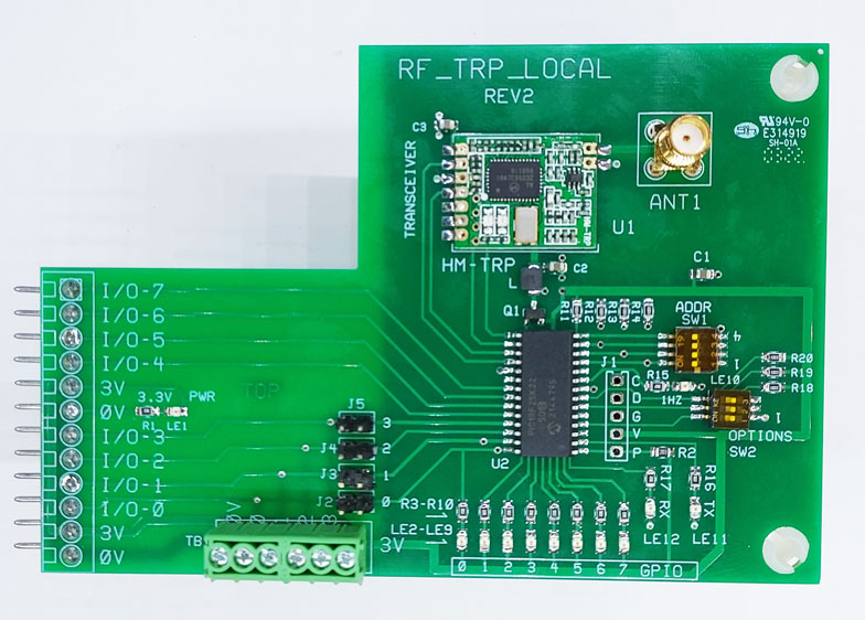
Note: Antenna Included!
This board is used to 'remote' most HMS interface boards with 'Phoenix' GPIO connector using the 'RF-TRP-REMOTE' board.
Or, the 'Remote board' can be used for direct connections (switches/motion detectors) without another HMS board.
Or, this 'Local' board can be used to control another 'Local board' for wireless interface to 1 or more BrightSigns!
Note: OPTIONS on the 'Local' and 'Remote' transceivers have to match!
SW2-1 'Off' and SW2-2 'Off' Selects 'Slave Mode' (the remote controls the GPIO inputs of the BrightSign.
SW2-1 'On' selects 4x4 mode (4 inputs and 4 outputs).
SW2-2 'On' selects 'Master Mode' (8 GPIO pins of the BrightSign are transmitted to any transceivers in 'Slave' mode.
SW2-3 'On' Selects 'No ACK' (no acknowledge bytes). This selection is useful when mulltiple 'masters' or 'slaves' are present. This selection may also be useful if a low noise environment and/or short distance between transceivers.
Note: with SW2-1 and SW2-2 both on, power on is inhibited. This is required to protect the transceiver during programming because 5V is applied to the board during programming of the firmware.
Slave Mode (SW2-1 and SW2-2 both off): The 'Remote' transceiver controls all 8 GPIO pins going to the BrightSign. (see 'Local Inputs' for exceptions). The 'Remote' transceiver transmits changes to it's GPIO.. If SW2-3 is off, then the 'Local' transceiver sends back the bytes for verification (see 'ACKnoledge' below). IF SW2-3 is on, then no 'ACK' bytes are sent back. This mode is recommended when multiple 'Master' or Slave' transceivers are used.
(4x4 Mode) (SW2-1 is on): 4x4 mode sets GPIO pins 0-3 as inputs to the
BrightSign and sets GPIO pin 4-7 as outputs to this 'Local' transceiver.
On the 'Remote board' GPIO pins 0-3 are used as inputs and those 'states'
(high/low) are sent to the BrightSign. GPIO pins 4-7 are sent to the
Remote board to control outputs 4-7 of the Remote board. This mode
conveniently allows the "Remote' transceiver to interface to many HMS 4x4
boards.
Note: SW2-2 is not read if SW2-1 is on (only 1 mode is allowed)
SW2-2 on (Master Mode) This mode allow the BrightSign (via the trancsceiver) to send all 8 GPIO pin states to the Remote transceiver or to another 'Local' board on another BrightSign. This feature allows wireless GPIO from one BrightSign to another. See 'Local Connections' for exceptions
If 'local connections' are required, then remove the jumper associated with the connection: Removing the jumper disconnects the associated I/O of the microprocessor to prevent damage to the microprocessor.
Remove jumper J2 if GPIO-0 is connected locally.
Remove jumper J3 if GPIO-1 is connected locally
Remove jumper J4 if GPIO-2 is connected locally
Remove jumper J5 if GPIO-3 is connected locally
Comment: The jumpers can be removed for any mode of the board (Master,Slave or 4x4). Be sure to set the direction of the GPIO pins of the BrightSign to match the board settings. I.E. Suppose that 'Master Mode' is selected but you need to use one or more GPIO pins 'locally'. These jumpers allow for 'disconnect' to the microprocessor of the 'Local board' so that 'Local Connections' won't conflict with the microprocessor pins.
Channel Selection |
|||
| SW1 | SW2 | SW3 | Channel# |
| OFF | OFF | OFF | 1 |
| OFF | OFF | ON | 2 |
| OFF | ON | OFF | 3 |
| OFF | ON | ON | 4 |
| ON | OFF | OFF | 5 |
| ON | OFF | ON | 6 |
| ON | ON | OFF | 7 |
| ON | ON | ON | 8 |
Note: If more channels are required (up to 16), contact technical support. SW1-4 was originally intended for address selection but was re-programmed for the Cycle diagnostic.
SW1-4 'On' Selects a Cycle diagnostic:
Note1: only set SW1-4 on the 'Local' or 'Remote' board (not both). This
makes the local board the 'Master' so be sure to set the remote board to 'Slave'
Note2: Running a program on the BrightSign with this diagnostic running could
interfere with the diagnostic.
The diagnostic sets all the GPIO as outputs on the LOCAL board. This may conflict with a program running on the BrightSign. The BrightSign should not be running a program! The outputs are cycled thru GPIO-0 thru GPIO-7 sequentially (one at a time). The state of these outputs is transmitted to the 'Remote' board.
Operation:
Slave Mode: (SW1-1 and SW1-2 both OFF) If this 'Local board is set to Slave (normal mode) then the Remote board is in control of all 8 outputs to the BrightSign.
Master Mode (SW1-2 ON and SW1-2 OFF). Then this board transmits all 8 GPIO of the BrightSign to the remote 'Slave' Be sure to set SW1-2 to ON on the remote.
In 4x4 operation, the lower 4 inputs (GPIO-0 thru 3) are programmed as outputs and the upper 4 GPIO (GPIO-4 thru 7) are programmed as inputs. When any of the BrightSign GPIO-4 thru 7 change state, the new state of those pins will be transmitted to the 'Remote' unit. The remote unit outputs (GPIO-4 thru 7) which mirror the state of the GPIO4 thru 7 on the BrightSign.
The lower 4 GPIO (GPIO 0 thru 3) are controlled by the remote. As inputs 0-3 on the remote change state, the change is transmitted to this receiver and output to the BrightSign. Jumpers are provided to disable connections to the microprocessor is local inputs (switches) are necessary. Be sure to pull any jumper associated with a local input requirement!
Note: All GPIO pins are active low (0). The 'assumed' off state is high (1).
*******************************************************************************
Acknowledge Switch (SW2-3): With this switch off, then the acknowledge bytes are returned to the transceiver. With this switch off, the 'master' tries up to 3 times to get the verify bytes (acknowledge bytes) from the slave. If not successful, then the Hz led flashes at 5 Hz (transmission error) for about 5 seconds.
Author: Richard Harkey
Revised: August 27, 2024