![]()
RF-TRP-4BUTTON (SET)
Wireless Interface of Buttons (switches) to the BrightSign with Phoenix GPIO connector
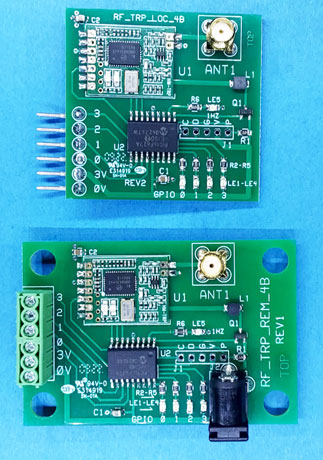
Note: Antenna Included!
This board set is used to 'remote' interface 1 to 4 buttons (switches) to control a BrightSign.
Order adapter TB12-DB15 for connection to legacy BrightSigns with DB15 GPIO connector
Fixed address. Contact HMS Electronics 'Technical Support' if you require custom addresses due to close proximity of wireless sets!
Operation:
The 'Remote' unit begins transmitting when any GPIO pin on the remote board goes low (switch or 'button' closure). It transmits continuously (every 20 milliseconds) the state of the GPIO pins as long as any pin in low. When all GPIO pins are high, then the remote transmitter transmits 'all gpio off' 2 times. Then the remote unit goes back to standby waiting for any GPIO to go low.
The 'Receiver' (connected to the BrightSign) drives 1 to 4 of the GPIO pins low corresponding to the transmitted 'GPIO byte' from the remote. The receiver connects to a Phoenix terminal block (not provided) and plugs into the back of the BrightSign.
Note: The transmitter receiver 'TRP' modules have LED's to indicate the state of the module. When transmitting the Remote unit 'Red LED' is on. When receiving the 'Local' Green LED is on.
Note: For reliability the communication consists of 3 bytes. Address, GPIO byte, Checksum. This protocol improves reliability and provides for custom addressing if required.
Note: The 6 pins of the 'Local' board can be connected to a 6 pin or to a 12 pin Phoenix connector. The upper GPIO's (4 thru 7) can be used if plugged in to the BrightSign connector in that manner.
Note: Order the phoenix connector seperately!
Author: Richard Harkey
Revised: August 27, 2024