![]()
 |
 |
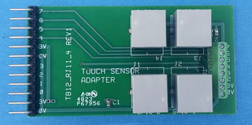
TB12-RJ11-4 |
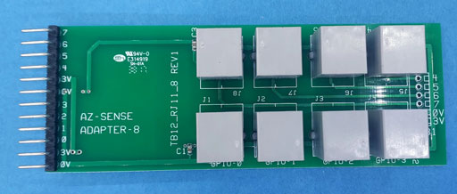
TB12-RJ11-8 |
Features:
These adapters have terminal blocks for additional connection.
RJ11-4 has an 8 terminal block for 0V, 3V, and GPIO 2-7. Use GPIO-2 or GPIO-3 connections if no sensor is plugged into the jack.
RJ11-8 has a 6 terminal block for 0V, 3V and GPIO 4-7. Use GPIO-4 thru GPIO-7 for connections if no sensor is plugged into the jack.
Wire Identification:
| Use These adapters if there is not room behind the BrightSign to attach the 'Series 3' adapters. This will require the purchase of TB12-DB15 adapter in order to use the DB15 cable. Order Adapter and cables for these adapters. | ||
 |
|
 |
|
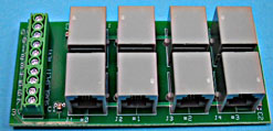
GPIO-RJ11-4-TB Adapter |
GPIO-RJ11-4 Adapter |
GPIO-RJ11-8 Adapter |
|
|
|
|
|
|
|
|
'AZ-Sense-Split' Adapter Use this adapter if you want to use the RJ11-4 phone connectors and using an HMS-I/O board with terminal block. Use a 10 conductor cable (for 8 sensors) to connect from this board to the HMS-I/O board. I.E. You can use an 8 input or 16 input 'HMS' board with this adapter. Works with 3V or 5V from the HMS Board.
|
||
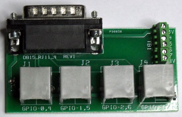
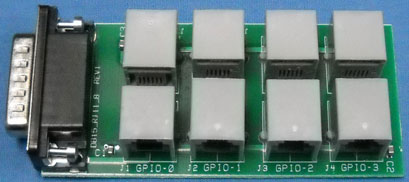
These adapters are designed to attach to the Proximity/Touch Sensors to the GPIO connector of the BrightSign (screws provided for direct mount to the GPIO connector for the older machines). Up to four or eight sensors can be connected to the BrightSign using these adapters.
GPIO-RJ11-4: The four Sensor connectors goto GPIO 0,4 and 1,5, and 2,6 and 3,7. The connectors also have an extra wire (future use) that connects to GPIO 4, 5, 6 and 7 respectively. This 'extra connection' may be utilized for back-lighting or 'double sensors' in the future. There is also a terminal block on the GPIO-RJ11-4-TB with 0V, 3V, GPIO 4,5,6 and 7 connections.
Note: Dual Sensor Boards coming (???) to be used with the GPIO-RJ11-4 adapters.
GPIO-RJ11-8:
This adapter will allow attaching up to 8 of the AZ-Sense2 single sensor boards using the phone cable connections at both ends.
Contact HMS Electronics 'Technical Support' for questions related to the 'Capacitive Touch Sensors'.
The current draw on the sensor module is very low so cable length has almost no effect on sensor operation. Maximum cable length has not been determined. However, 100 feet (30 meters) is a distance that the module should work with. We suspect that the sensor could be 300 feet (100 meters) or more.
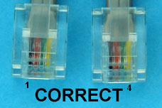
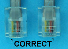
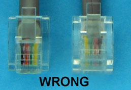
The RJ11 phone cable ends need to have the same 'polarity'. Meaning, all pins of the plugs need to have the same color wire in both ends. Here are a couple of pictures to help with identification of 'polarized' phone cables.
Note: If not using the RJ11-4-4 or RJ11-4-8, then cut and strip the 4 wires for attaching to a terminal block.
RJ11-1. Tie all 3.3V-5V wires together and connect to 3.3V or 5V on the HMS Interface board.
RJ11-2. Connect each 'Sensor Output' to the appropriate input of the HMS Interface board.
RJ11-3 + RJ11-4. Tie all 0V (RJ11-3) and 'Spare' (RJ11-4) together and connect to 0V on the HMS Interface board.
Note: DB15-TB10-3V adapter is a suitable interface for connections.
Author: Richard Harkey
Revised: August 27, 2024