![]()
4 Isolated inputs (Buttons) via Opto-Couplers and 4 Each 2A outputs
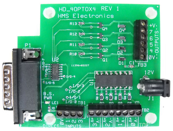
HD-4OptoX4 ,Opto & Light Driver I/O Board
Features:
This board solves the need for using a relay to convert a control signal of 12 or 24 volts DC to a switch closure. The BrightSign only works with 'switch closure' to 0Volts to activate the GPIO inputs. The opto-couplers convert the 5, 12 or 24 volt input to a 'switch closure' to operate the GPIO inputs (BTN0-BTN3). When the voltage is applied to the opto-coupler, the output of the opto-coupler turns on (same as closing a switch to the BrightSign)
There are two terminal blocks for inputs. One terminal block is used to control the 4 Opto-Couplers (see schematic). The other terminal block allows for bypass of the opto-couplers so that normally open switches can be used as well. The opto-couplers are like normally open switches so you can parallel the output of the opto-coupler with a switch using the second terminal block as inputs
Opto-Isolator Inputs: There is an 8 pin terminal block marked with +V and 0V for each of the 4 inputs. The 4 inputs are labeled 0-3 (this corresponds to Btn0-Btn3 of the BrightSign). This board is utilized when another device applies 12 volts or 24 volts to turn on a remote device (the BrightSign).
Set GPIO 4-7 low to turn on outputs 4-7
Author: Richard Harkey
Copyright © 2009 HMS Electronics. All rights reserved.
Revised: August 27, 2024