![]()
4 Isolated inputs (Buttons) via Opto-Couplers and 4 Isolated outputs (Relays)
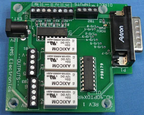
HD-4Opto-4R ,Opto & Relay I/O Board
Features:
This board solves the need for using a relay to convert a control signal of 12 or 24 volts DC to a switch closure. The BrightSign only works with 'switch closure' to 0Volts to activate the GPIO inputs. The opto-couplers convert the 12 or 24 volt input to a 'switch closure' to operate the GPIO inputs (BTN0-BTN3). When the voltage is applied to the opto-coupler, the output of the opto-coupler turns on (same as closing a switch to the BrightSign)
There are two terminal blocks for inputs. One terminal block is used to control the 4 Opto-Couplers (see schematic). The other terminal block allows for bypass of the opto-couplers so that normally open switches can be used as well. The opto-couplers are like normally open switches so you can parallel the output of the opto-coupler with a switch using the second terminal block as inputs
Opto-Isolator Inputs: There is an 8 pin terminal block marked with +V and 0V for each of the 4 inputs. The 4 inputs are labeled 0-3 (this corresponds to Btn0-Btn3 of the BrightSign). This board is utilized when another device applies 12 volts or 24 volts to turn on a remote device (the BrightSign).
The new Rev 2 board uses 'low signals' to turn on the relays. The
BrightSign powers up with the GPIO's all set to inputs with internal pull-up
resistors. The GPIO has all 'high' signals to the relay turn-on circuits.
The new board takes care of the relay problem (all on when power is applied) by
inverting the GPIO signals that control the relays. Now set the GPIO (4 -
7) low to turn on the associated relay.
Gpio-4 low, turns on K1
Gpio-5 low, turns on K2
Gpio-6 low, turns on K3
Gpio-7 low, turns on K4
Note: Relay outputs are just a closed set of contacts. See the schematic for connecting 12V or other external voltage to the contacts to control external devices.
Important: It may be necessary to add a snubber network across the terminal blocks when switching AC loads. The 'electrical noise' of relays switching could reset the BrightSign. The 'snubber' network should be a 100 ohm 1/2 watt resistor and a .022 micorfarad capacitor in series. The capacitor voltage rating needs to be 2.2 times the applied voltage. I.E. for 230V, the capacitor should be rated to 500 volts.
Important: For DC loads, a diode has to be connected across the load (see the schematic)
Note: Snubber Networks are available on the ordering page for this product.
Link: Schematic
Author: Richard Harkey
Copyright © 2009 HMS Electronics. All rights reserved.
Revised: August 27, 2024