For 'Series 3' BrightSigns with USB Port or Serial Port
DMX Controller
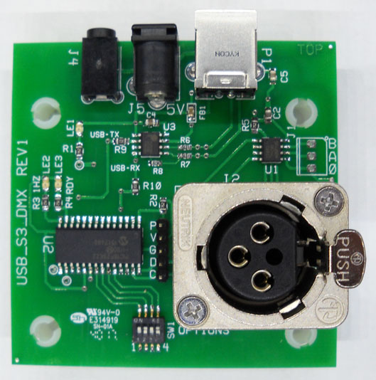
USB-S3-DMX
Features:
- Small footprint (2.8 x 2.8 inches)
- Power thru the USB or 5V external 2.1/5.5mm jack using 5V
- On board LED's to indicate Power and Processor running.
- Serial Setup: 38,400 Baud, N,8,1 (standard RS232 communication)
Overview:
The USB is connected thru a USB-Serial 'Prolific' converter chip. This
board appears as a serial device to the BrightSign. In BrightAuthor, be
sure to set the Presentation Properties/Serial port to Port2 for the USB device.
Use 'Port0' for the serial connection Version 7.xx firmware no longer requires
'invert levels' at the BrightSign!.
Operation:
This board uses the 'HMS Protocol'. Fade for DMX Channels or
'Non-HMS Protocol selected by SW1-1
Version 6.x Firmware: SW1-3 selects the baud rate. SW1-3 off
sets 38,400 baud. SW1-3 on sets 115,200 baud
Note: The baud can be changed dynamically (without re-set of the board)
****************************************************************************************************************
New Version 7.0 Firmware features
1. New 'Auto Detect' of 'polarity'. This feature enables connection
to a standard serial port without the need to invert the signals at the
BrightSign.
2. New 'Auto Play' of a DMX scene at power up. This feature sets up
the board to play scene 48 if the first byte of scene 48 is 26 (setup DMX
channels)
To setup this feature you need to use the command 'Record Scene' (33,48,204)
followed by command 26 bytes 26, #bytes, start channel, byte1, byte2 to #bytes
I.E. To set Channels 1 thru 4 to have a default value on power up:
33,48,204,26,4,1,255,0,255,0. This sets channel 1 to 255, channel 2 to 0,
channel 3 to 255, channel 4 to 0.
*****************************************************************************************************************
Serial Transmission 'Break' Protocol: The serial port
(BrightSign) has to allow 20 milliseconds to elapse between serial data 'bursts'
going out. This 20 millisecond 'rest' time is interpreted by the HMS board
as a 'Break' in serial transmission. This 'Break' condition synchronizes
the HMS board to the serial transmissions from the BrightSign (or other device).
New Command Selection for HMS Protocol: The first byte received by
the HMS board (after 'break condition') sets the receive protocol command.
This new protocol simplifies how many bytes to send from the BrightSign because
the DMX parameter is selectable! The bytes are enclosed in brackets [ ]. Note:
'Speed' = Rate of Fade.
Note: See the 'Not HMS Protocol' for simple DMX
control (no fade) near the bottom of this specification sheet.
*********DMX SPECIFIC COMMANDS 16-26, and 31
- Command16: Set DMX Channel Values (Starts at Channel 1)
? bytes [16, #Bytes, DMX_CH1 to DMX_CH100], followed by 'Break'
if '#Bytes' was not received
- Command17: Set Multiple DMX 'Fade Channel' values
? bytes [17, #Bytes, Channel#,'Channel Value', 'Fade Value',
Channel#, 'Channel Value', 'Fade Value',....], followed by 'Break' if '#Bytes'
was not received.
- Command18: Set 1 DMX 'Fade Channel'
3 bytes [18, Channel#, Channel Value, Fade Value]: *1 End
Command
- Command19: Set all 24 DMX Fade values to one value
2 bytes [19, Fade Value] *1 End Command
- Command20: Set the 24 DMX 'Fade Channels' to a pre-set Fade Speed
(values have to be in Channel order!)
17 bytes [20, Ch1_Fade Value, Ch2 Fade Value,... to Ch24_Fade
Value], followed by 'Break' unless all 24 Fade values are sent
- Command21: Set 1 or more DMX channels to a value.
? bytes [21, #Bytes, Channel#, Value, Channel#, Value....],
followed by 'Break' if all the bytes ('#Bytes') was not received
- Command22: Set 1 DMX channel to a value:
New: With Version 4.x firmware setting channel 0 sets channel 512 value
3 bytes [22, Channel#, Value] *1 End Command
- Command23: Set all 512 DMX channels to one value (channels 1 to
512)
3 bytes [23, Channel Value,204] *1 End Command
- Command24: Set all 24 DMX ' Fade' channels to one value (channels
1-24)
3 bytes [24, Channel Value,204] *1 End Command
- Command25: Set all 512 DMX 'Non Fade' channels to one value.
3 bytes [25, Channel Value,204] *1 End Command
- Command26: Set starting DMX Channel#, first byte to this channel,
successive bytes to successive channels. Well suited to DMX Head Controlling!
? bytes [26, #Value Bytes, Start Channel#, Value1, Value2,
more values to #Bytes], followed by 'Break' if '#Bytes' was not received.
- Command27: Set Default Fade Value for Power-up (Value stored and
retrieve at power up)
3 bytes [27,Fade Value, 204]
- Command28: Set All 512 DMX Channels off Instantly (Does not affect
the Fade Values)
2 bytes [28,204]
- Command29: Set the maximum number of DMX channels to transmit (the
default is 50). This value stored in permanent memory.
3 bytes [29,Max Channels, 204] Note: a value of zero (0), enables
512 channels (Fade should be not set below 30 when 512 channels is enabled).
- Command30: Set one 'upper' DMX channel to a value (upper channels
are 256-511). A value of zero sets channel 256, a value of 1 sets channel 257
and so on.
3 bytes [30,Channel#,Value]
- Command31: Set multiple 'upper' DMX channel values.
?? bytes [31,Start Channel, value, value...,170] Note: 170
terminates the command because we have an unknown number of bytes to set.
Note: The 'Start Channel' is added to upper channel 256 (location in memory is
0x200 (page 2 of memory). Note: To use this command as a 'play command' the
last byte has to be 170d which will terminate this command.
- Command37: Set/Clear DMX512 Flag (setting this flag enables
'overlap' of successive scenes so that upper channels are part of the 'play
scene command'
2 bytes [37,0] clears the flag, [37,1] sets the flag
- Command38: Set successive Fade Channels
??bytes [38,#bytes,start
channel,brightness,fade,brightness,fade....#bytes) Similar to command 17 but
only the start channel is required.
*********Play/Record and Other 'Scene' Commands 32-36
Link to 'Scene
Format (Protocol)'
- Command32: Play 'Recorded' Scene
3 bytes [32, Scene# (1-48), 204] Note: Contact HMS Electronics
for a 175 scene board.
- Command33: Record 'Scene' (256 byte limit) (Scenes
can be concatenated)
[33, Scene# (1 to 48), 204, 1 to 256 bytes] Note:
Contact HMS Electronics for a 175 scene board.
- Command34: Cancel 'Play Scene'. This command should
be issued prior to any new command if Command32 was last command. This
insures that the 'Play Scene' Command is stopped.
2 bytes [34, 204]
- Command35: Erase Scene (erase all scene bytes)
3 bytes [35, scene#,204]
- Command 36: Set DMX Scene (3.1 firmware). This
'scene' command sets all 256 channels from a scene number. This scene for DMX
can be set using the 'Record Scene' command above.
3 bytes [36, scene#,204]
********Miscellaneous Commands (Useful for Development)
- Command 39: Say 'Max Channels' = ", max_channels (this is text to
the computer) followed by the number of bytes to transmit
- Command43: Send the Data for DMX channels 1 to 'Max
Channels' to the computer
[43,204]
- Command44: Send 'Scene Data' to Serial Port: All
256 bytes of the scene are sent out the serial port. Very useful for verifying
command 'data strings'.
3 bytes [44, Scene# (1 to 48), 204]
- Command45: Report the Software version of the board
to the Serial Port
2 bytes [45,204]
- Command46: Report the Goals and Fades for the Fade
channels. I.E. Goal 1, Fade 1, Goal 2, Fade 2,....to Fade 24, Default fade,
Max_channels (see Cmd29), Upper channels ( see Cmd37)
2 bytes [46,204]
- Command47: Firmware Upgrade Command (the HZ LED
will flash at 5 Hz) (use the 'HMS_Downloader.exe' program to update the
firmware). Contact HMS Electronics to see if there is a firmware upgrade and
report the current firmware revision when requesting this information.
2 bytes [47,204]
*1: All commands that end with 204 (the end command byte) or are stated in
the description ('End Command') is the end of the command and another command
can be part of the same string (no 'Break' required)
I.E. Turn on DMX channel 1 100%, Turn on DMX channel 50 100%
[22,1,255,22,50,255] (Two command22's in succession)
Notes:
- Any 'Command' followed by a 'break condition' terminates the Command. So,
if zero bytes follow Command=16, Command 16 will simply be terminated at the
break condition.
- If you use 255 for the #bytes, then the command will be terminated at
'Break' and fast flashing (Hz LED) will indicate that the command did not
terminate correctly (#bytes was not received).
- The brackets are not part of the byte sequence! Send decimal bytes no
strings!
- If #bytes is less than the bytes you are sending as part of the protocol,
unexpected results will happen.
- Any 'illegal' command results in 'dumped bytes' until 'Break' condition.
So, if a large string of bytes is sent, and a channel fade number is out of
range (>24), then the remaining bytes of that string are discarded.
- To 'Concatenate' Scenes: see 'Scene
Format Protocol'
To Send Multiple Commands (not concatenated) , Send 1 command, then pause for
20 milliseconds, then send the next command and pause and so on except where
designated above.
Note: Fast Flash of the 1Hz LED (3 Hz). When any command is
terminated with 'Break', fast flashing occurs. When a command is sent
incomplete or out of range, (I.E. set fade for channel 30), because channel 30
is out of range, fast flashing is set. Fast Flashing is cleared upon
complete reception of a command not requiring the 'Break' condition. I.E.
Send 'Command0', to clear the fast flashing after 'Break'.
DMX512 Operation: The DMX first channel to 'Max Channels' channels (see
command31) are sent every .5 seconds if Option2 is off) or whenever the DMX
'Channel' bytes change (resulting in instant DMX output). The DMX512
protocol is so fast that the entire 256 (256 channels) channels of DMX data can
be sent out in 14 milliseconds. 512 channels are sent in about 28
milliseconds.
DMX 'Head' Operation. If a DMX dimmer pack is utilized,
setup the dimmer pack to utilize channels 1-4. Then set the DMX 'Head'
start channel to 5 (or whatever channel is allowed). If the DMX 'Head' is
the only DMX device, then set the 'Head' channel to channel 1. If the DMX
'Head' protocol expects to receive 20 bytes (20 channels) then all 20 of those
bytes need to be sent with each DMX 'Head' command sequence. Likewise,
when using the BrightSign to control the DMX Head, the BrightSign should send
all 20 DMX bytes with each Serial Send() command. If the DMX512 'Head' can only
be set for 'even addresses' or multiples of a number (I.E. 20,40,60) then the
bytes for that address (channel) will have to start at the address or channel
set as the base channel.
DMX 'Play Scenes'. A 'scene' file can be created and stored on the SD
card. BrightScript would be used to interpret the 'scene file'. Any
number of scenes could be stored on the SD card. Contact the BrightSign
people if you need help with this programming.
 DMX_Demo.AVI (84 mega byte movie demo)
DMX_Demo.mov 6MB (requires Quicktime) Link:
Setting up the Serial Port and Sending Bytes with 'BrightAuthor'.
DMX_Demo.AVI (84 mega byte movie demo)
DMX_Demo.mov 6MB (requires Quicktime) Link:
Setting up the Serial Port and Sending Bytes with 'BrightAuthor'.
HMS-RS232-DMX.brs
(sequences channels 1 thru 4). Rename this file to 'autorun.brs' and put it on
the SD card
*****************************************************************
Note: The brackets are not part of the byte sequence.
Options: (SW1)
- SW1-1 Off = HMS Protocol enabled (uses the 'command structure' explained
above).
- SW1-1 On = HMS Protocol disabled. The byte sequence is [DMX_CH1_byte,
successive DMX channel bytes]
- SW1-2 OFF = Normal Serial Polarity (USB Compatible)
- SW1-2 ON = Invert Serial (For compatibility with the TTL serial port of
the BrightSign)
- SW1-3 On = Repeat DMX continuous.
- SW1-3 Off = Send DMX bytes every .5 seconds or as the DMX bytes change
(command changes or fade changes).
- SW1-4 On = Cycle Diagnostics ( Turns DMX channels 1-100 full on, then off
every .6 seconds)
| Note: External Supply Voltage: IF the USB
connection is not used to supply power to the board, then use an External
Power Supply of 5V. |
Last Revised:
08/27/2024