![]()
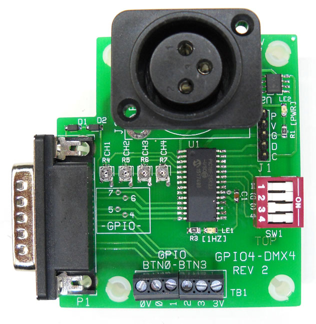
GPIO4_DMX4_R2
Features:
Because the HD120 only has a GPIO port for external connections, this board was designed as a low cost method of adding DMX to the the low cost BrightSign HD120. Use this interface board to control DMX channels 1 thru 4 (with fade). Fade rate is selected using SW1 switches 1-3. When the associated GPIO output goes low, the channel associated with that input turns on.
Note: With this scheme (channels 5 to 8 are instant, if you set the dimmer box (DMX Receiver) to channel 3 (instead of channel 1) then channel 3 and channel 4 will adjust with fade with GPIO-6 and GPIO-7. Channels 5 and 6 will turn on or off (instant) with GPIO-4 and GPIO-5.
Note: DMX Brightness is set to to the value of the potentiometer. Full Brightness is 255, Minimum Brightness of about 20. The adjustment is dynamic (adjusts brightness with the light on).
*****************************************************************
Note: Only Channels 1-4 have the 'Fade Control' (fade rate of change of brightness).
Fade value is the number of milliseconds that it takes to adjust to the next number nearer the brightness setting for the channel. A fade value of 4, means it takes 4 milliseconds to change from one value to the next value. So to go from 0 to 255 (off to full on) at 4 millisecond fade rate, it takes 4*255=1000 milliseconds (1 second).
Note: Each channel on/off is independent (can fade at different times). The channel begins fade from the moment that the GPIO input changes state.
SW1-4 (on) selects a 'cycle diagnostic (firmware 3.0). All 100 DMX channels are turned on for 1 second then turned off for 1 second. This diagnostic is useful to confirm wiring. This diagnostic requires the board to be powered via the BrightSgin. Or, the board can be powered using 3.3V supply to 0V and 3V of TB1. When power is applied, the '1HZ' led should be flashing.
See the document on DMX-512 for a description of DMX dimmer pack use and implementation.
Note: This procedure will not damage the BrightSign. Insert a piece of wire to TB1-0V (not '0'). With the BrightSign powered up and the board connected touch the other end of the wire to GPIO-4 near the DB15 connector. This action makes GPIO-4 appear low to the board and will trigger DMX channel 1 to turn on. Similarly, touch the wire to GPIO 5,6 &7. This action should trigger DMX channels 2,3 & 4 to be on. The Brightness potentiometers and fade switch can be set at this time to provide the lighting action that best suits your application.
Note: If touching the wire to GPIO-4 does not activate DMX Ch1, but the diagnostic works (all 100 channels flashing), then the DMX Controller is likely not set to Channel 1.
Last Revised: 08/27/2024